|
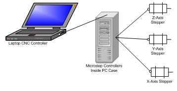
The interface is pretty simple. A PC running control software handles the logical side. The controller will move the motors per the PC's commands. An old PC case is handy because the power supply can be modified to power the drivers and the motors. The parallel port on the pc will signal step and direction - the driver will actually step the motor in the correct direction by alternating current and voltage to the motors coils. |
|
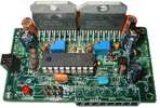
For the controller, I've chosen to use the
Microstep design from EAS. Using the 8 microstep mode with my 1.8 degree steppers (200 full steps/rev) I get 1600 steps per revolution. Combined with .2"/revolution ball screws I'll actually achieve .000125" per microstep. Manual Schematic layout Parts list |
|
|
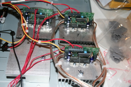
The controller is built into a small pc case Each microstep has it's own heat sink. Each one gets power directly from the power supply The spare is for adding a fourth axis later on. wiringThe yellow wires provide 12 volts to the motorsThe black is ground - which is the same bus on the microsteps, so only one wire is needed The red wire providies 5v directly to the pic circuitry. This bypasses the 7805s onboard. The speakerwire was the only thing thick enough to carry full current to the stepper motors |
|
|
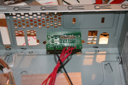
Control signals come into the breakout board. A DB-25 straight through cable connects to the pc. I forgot to order the resistor network, so I made one |
|
|
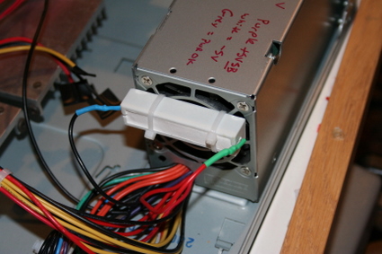
The power supply is a smaller form factor ATX psu. The white part is a 271-120 20 watt 8 ohm resistor from radioshack. It's connected to the 5 volt bus to force the psu to produce enough current on the 12V bus. |
|
|
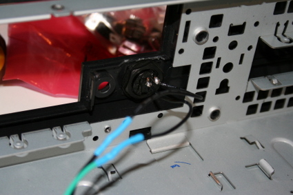
The power switch is a spare I had laying around. It's mounted to the front cover of the pc case. It's wired to the green psu lead (power enable) and one of the ground leads. When the green wire is grounded by the switch, the power supply is turned on. |
|

|
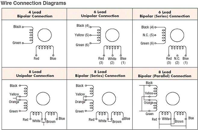
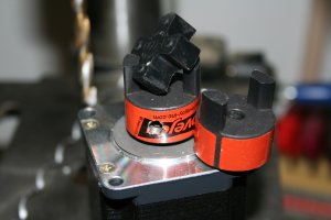
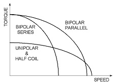
I picked up a pair of 190oz/240oz (unipolar/bipolar) Vexta PK268-E2.0A stepper motors for the X and Y axis off ebay. The specs are in the datasheet, but I'll run down the key bits here. |
|
|
|