These ball-nut stops replace the original brass acme nuts.
Rather than spend $20 on a 15/16-16 tap from wholesale tool,
I paid Hoss to make me a set of ball nut stops and to modify the Z-axis pully.
He did a great job, and I've got no regrets there.
|
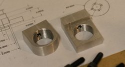
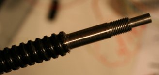
I decided to keep a bit of my sanity during the project. These ball-nut stops replace the original brass acme nuts. Rather than spend $20 on a 15/16-16 tap from wholesale tool, I paid Hoss to make me a set of ball nut stops and to modify the Z-axis pully. He did a great job, and I've got no regrets there. |
|
|
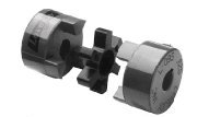
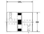
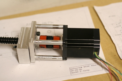
Hoss made some aluminum couplers. I wanted some flexible couplers that would avoid binding I got the idea to use lovejoy couplers from this conversion I ordered my lovejoy spider couplings from Enco. OD=1.08", OAL=1.72" I bought 1/4" hole hubs, and Buna-n spiders Part numbers: 990-4044 (hubs) x4 990-4042 (spiders) x 2 |
|
|
I used his spec, but made a couple of changes. I didn't use a 1.1" y spacer - I used a 1.0" y spacer. It was easier to buy and needed less machine work. I compensated for the thinner spacer when I turned the Y ballscrew in my lathe. I also turned down 1/4" the opposite end of the ballscrew to fit inside the carboard spacer that comes inside the Nook ballnuts - allowing me to remove the Y ballscrew without pulling the saddle to make some adjustments later on. Finally, I turned the ends of the ballscrews down to 1/4" to match the lovejoy couplings. (I wanted to keep parts homogenous) |
|
|
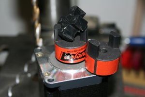
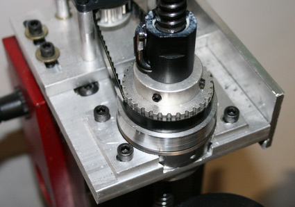
The z-axis is mostly just like Hoss's build. I didn't cut off the corners, and I made everything from 6061 aluminum instead of cold rolled steel I turned the bearing spacer and retainer on my mini lathe with carbide brazed toold. I had hoss drill and tap the pulley for me. I used nearly the same pulley, but mine lacks flanges. The bearing spacer acts as a lower flange, so it's not an issue. To align the pulley, I chucked the bearing spacer, put slow CA adhesive on the pulley Then used the tailstock of the mill to press the two together and provide alignment. Once it set, I drilled and tapped the four screw holes that secure the pulley See the updated Z axis below |
|
|
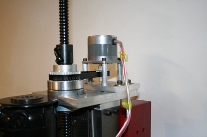
I redesigned the Z axis ballscrew mount out of neccesity. I haven't gotten around to picking up a drill chuck for the tailstock Until I get it, I have no way of accurately drilling and tapping a hole in the end of the ballscrew. Instead, I turned the screw down to .5", then cut a .5" hole in a 3/8" plate. Then I milled a flat notch into the part I turned down. I added a 1/4" set screw to hold the ballscrew in. So far it's good. I'm getting the chuck ASAP, but I'll probably wait until it fails before I rebuild it. |

|
|
Once the last motor came in, I started thorougly testing the Z axis. It had alot of flex in it. I added a stiffener to the side (not really neccesary The main improvement was the addition of the two small brackets on either side of the bearing. I cut the inset too much, so the bearing was sliding around too much. Now it stays pu. The play in the large bearing was causing funky slack in the belt drive. Additionally, I had to put the inner bearing spacer that the pulley is mounted to on the lathe and true it up a bit. Somehow I managed to leave an uneven surface before. I added some lock-tite to the two main hold down screws, and plan to add another side bracket to the stiffener. The bracket will connect the stiffener to the column for extra stiffness. Until I trued up the spacer, the assembly had a tight spot as it turned. |