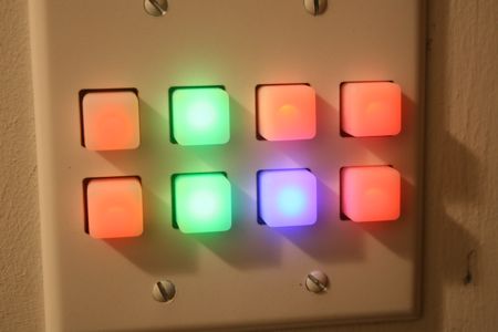
RGB Keypad door lock
This page is where you'll find the latest schematics, eagle cad files and Arduino code for my RGB keypad.
You can also order pre-cut wall plate bezels from this page.
Schematic and PC Board design
Here's a
large jpeg of the schematic.
Here's the Eagle CAD schematic.
Here's the board design for Eagle.
The board design will be released when part 2 of the how-to is published on Hack-A-Day.
Release notes: I was lazy and didn't try to use the ground symbol on the schematic - The grounds are all connected on their own NET. Sorry if it's confusing.
When I have time I'll take a shot at improving the schematic a bit.
Arduino code
Click each example, select the text and copy and paste it into a new sketchbook on your Arduino software. Then upload and have fun.
Button test:
button_test is a simple arduino program. I wrote it to help debug my keypad. It watches for button presses. On each press the Arduino will print a debug message on the serial port. It will also toggle the state of the electric lock output.
RGB light fade:
RGB_light_fade is actually written to light up a 4x4 pad. It's great for testing out all of the LED connections from the Arduino. Every LED should get randomly faded in and out. It's also a good demo of the color mixing capabilities of the device.
Row entry pad meffect:
row_entry_pad_meffect is my current, simplified RGB entry pad code. It uses a simple color code. If entered correctly, the pad lights bright green and the door lock is opened for 10 seconds. If too many keys are pressed, the pad locks out bright red for 30 seconds. During normal idle time, the pad steps through each button and lights it up blue just for fun.