Arduino sine wave with a digital potentiometer

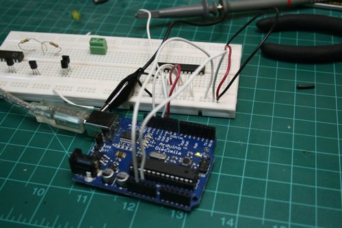
Arduino, Digital POT and an o-scope probe
I wanted to create a sine wave to test my ignition system with a better test signal, but I didn’t have a DAC handy. I did have a spare digital pot from my RGB doorlock project. There are several examples of DACs being built from resistor ladders, so I figured I’d give it a shot. The SPI digital pot tutorial made this pretty easy to set up.

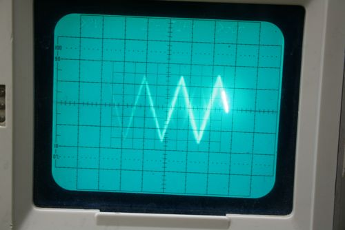
Rather nice sawtooth
Here’s what I managed to produce, using some code that stepped the resistance on one of the digital pots. After increasing the slope of the output by sending steps of 5 (out of 255) I ended up with this sawtooth pattern. With a bit more code I can probably produce a fair sine wave with the pot, but ultimately frequency will be limited by the speed of the SPI interface. To perform my test, I need a frequency that equals RPM/(60sec/min) * 36 pulses/revolution. At 1200rpm, thats 720Hz or 1pulse every 1.39ms. When you add in the extra writes to smooth out the curve, the digital pot trick will probably get close, but it’ll be pretty difficult to simulate something faster like 8000RPM (4.8kHz or every .2ms)